|
FP
SERIES
FOUR POST VERTICAL LIFTS
|
|
|
For
Heavy or
Bulky Loads
|
|
|
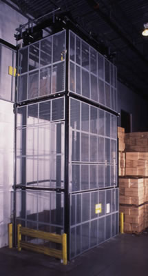
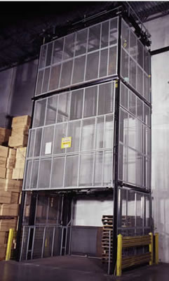
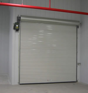
Four
Post style material lifts are designed for moving large heavy
loads and are
constructed from structural steel. These lifts utilize two (2)
100% duty-cycle brake
motors mounted at the top of the unit. The low noise all-mechanical
dual-drive
system safely transports the carriage and the load with ease
by means of four
(4) lifting cables. This style of lift is most commonly used
in large warehouses and
distribution centers for efficiently moving product between
two or more levels/
floors. These lifts require very little maintenance and have
increased longevity
over hydraulic lifts. |
|
 |
|
|
|
|
|
|
All
cable operated lifts are equipped with broken cable brakes to
prevent the
carriage from falling in the unlikely event of a cable failure.
Mechanical interlocks
prevent doors from being opened when the carriage is not present
at that level.
Dual electric brake motors secure the carriage in the event
of a power failure and
prevents the platform from drifting. |
|
|
|
|
|
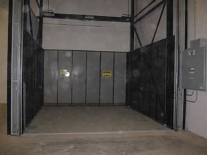
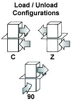
The
carriage is available in three load pattern configurations:
C, Z & 90. Standard
units have 48”H expanded metal platform side panels on
all on operating sides
and a snap chain across the access sides. Higher panels are
available. |
|
|
|
|
|
Operation
is controlled by a Call/Send Station mounted next to each door
at each
level. Each station is also equipped with a large E-Stop button
to stop the unit in
an emergency. |
|
|
|
|
|
Guarding
around the lift is required to meet safety codes. We offer metal
enclosure
panels and gates to meet your applications requirements. Different
options are
available for shaft installations. Safety enclosures are built
into the structure adding
rigidity and enhanced security. These enclosures are manufactured
from 2” angle
for the framing and covered with 1/2” expanded metal to
reject a 2” diameter ball
as required by code. |
|
|
|
|
|
|
|
|
|
 |
|
 |
|
|
|
|
|
Perfect
For |
|
|
•
Distribution
• Warehousing
• Balconies
• Military
• Manufacturing
• Through Floor |
|
|
•
Retail Stores
• Freight
• Mezzanines
• Automotive Parts
• Medical Facilities
• Printing |
|
|
|
|
|
|
 |
|
|
|
|
|
|
|
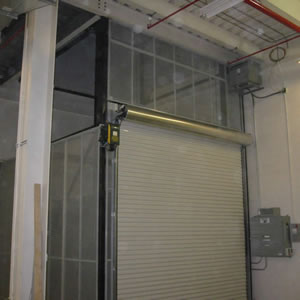
Top
mounted drive system
allows for a smaller
footprint than other styles
of lifts. |
|
|
|
|
|
|
|
|
|
|
|
|
|
|
|
|
|
 |
|
|
|
|
|
|
 |
|
|
|
|
|
|
|
|
|
|
|
|
|
|
|
Standard
Features
|
|
|
|
|
|
|
•
Load Capacity: up to 10,000 lbs*
• Platform Size: up to 12’W x 12’L*
• Travel Height: up to 30’
• Operating Levels: up to 4-Stops
• Operating Speed: 20-30 fpm
• Power: 230V/3P or 460V/3P
• Illuminated Controls at Each Level |
•
Fail-Safe Brake Motor
• All-Mechanical, Quad Cable Lifting System
• Cable Safety Brakes
• Slack Cable Switches
• Electromechanical Interlocks
• Soft-Start / Soft-Stop Operation
(Variable Frequency Drive) |
|
|
|
|
|
|
| Many
Options Available |
|
*Larger
Platform Sizes and
Capacities Available Upon Request
|
|
|
|
|
|
|
|
Contact
us for more information and a
free quote for your application
|
|
|
|
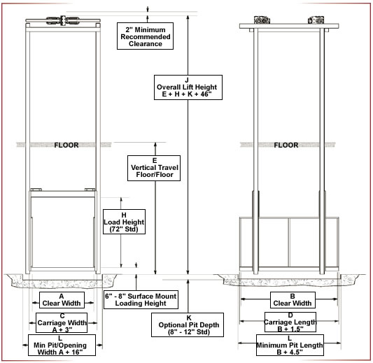 |
Surface
Mount:
The loading height is 6” or 8”
from the floor on the ground
level and flush with the floor
on upper levels. |
|
|
Pit
Mount:
Loading height is flush with the
floor on all levels (standard
pit is 8" - 12”). |
|
|
 |
|
|
|
Note:
Dimensions shown are for
reference purpose only and may
differ from your lift. Before making
any building modifications, contact
us to request a job-specific drawing.
Some limitations may apply. |
|
|
|
|
|
|
|
|
|
|
STRUCTURE
Guide rails are constructed from structural steel H-Beam.
Carriage uses steel channel for vertical members and
header. Carriage deck (platform) is built from solid
steel plate on a square steel tube frame. |
SAFETY
SYSTEMS
Fail-safe electric brake locks the carriage in place in the
event of a power failure. Slack cable switches shut off
the motor if the cables become slack. Broken cable brakes
prevent the carriage from falling in the unlikely event of
a cable failure. Limit switches provide accurate leveling
at each level. “NO RIDER” signs are on carriage and
at each entry point. Double swing interlocked gates
prevent access to the carriage while in motion and
when not present at that level. |
|
|
|
|
OPERATION
Illuminated push-button stations at each level allow full
call/send capabilities and inform the operator of carriage
position and notify of doors open. E-Stop buttons are
included in every call station. |
|
|
|
|
|
|
|
|
|
|
|
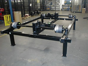
MECHANICAL
DRIVE
The carriage is moved by using two electric fail-safe brake
motors and reducers. Quad cables and drums provide
extra safety and durability. This drive system requires very
little maintenance. |
|
CARRIAGE
Carriage is usually built as one piece for added strength
unless platform size is 8’W or 8’D and larger. Platform
panels are provided on non-operating sides of the
carriage and snap chains on operating sides for safety. |
|
|
|
|
|
|
SECURITY
ENCLOSURES (OPTIONAL)
Panel and gate frames are constructed from steel angle
covered by 1/2” expanded metal. These enclosures
provide a means of protecting personnel from entering
the path of a moving lift. Double swing interlocked gates
prevent access to the carriage while in motion and when
not present at that level. |
|
ELECTRICAL
Control voltage is 24V for all switches and momentary
push button stations. Push button stations are
NEMA 12. |
|
|
|
|
|
Note:
To comply with ANSI/ASME B20.1 standard, proper
guarding on all accessible sides must in place during operation.
This is usually achieved by building a sheetrock/drywall shaft
or using optional enclosures. Our lifts are not subject to elevator
codes as they are designed for material lifting only. No personnel
are permitted to ride on vertical lift. |
|
|
|
|
The
following items are to be supplied by others and are not included
with the vertical lift:
(1) wall and floor hardware to secure the lift to the walls
and floors,
(2) external electrical wiring which is to be performed by a
qualified electrician to local and
national codes,
(3) the conduit and disconnect switch that is required to connect
our control panel and
(4) upper and lower thresholds. |
|
|
|
|
ARCHITECTURAL
SPECIFICATIONS
VERTICAL RECIPROCATING CONVEYOR
|
|
|
|
|
|
| PART
1: GENERAL |
|
|
|
|
|
|
| 1.01:
OVERVIEW |
|
|
A. Design and manufacturing of one (1) 4-post dual drive type
Vertical Reciprocating Conveyor (VRC) including
mechanical drive unit, operator controls, safety gates and enclosures
as shown on project drawings and as specified
herein. |
|
|
|
|
|
| 1.02:
REFERENCES |
|
|
|
|
|
|
|
|
A.
ANSI - American National Standards Institute (ANSI B20.1) |
|
B.
ASME - American Society of Mechanical Engineers (ASME B20.1) |
|
C.
NEMA - National Electrical Manufacturer's Association |
|
|
|
|
|
| 1.03:
SUBMITTALS |
|
|
|
|
|
|
|
|
A.
Product Data: Submit latest edition of 4-Post Dual Drive VRC
datasheet and general drawings with the proposal. |
|
|
|
|
|
|
B.
Customer Drawings: |
|
|
|
|
|
|
|
1.
Submit Customer Engineering Drawings for customer approval within
2 weeks after receipt of an order to include
plans, elevations, sections of the VRC, base plate and lateral
loading values, and recommended pit dimensions if applicable. |
|
|
|
|
|
|
|
2.
Submit VRC Specification Sheet for approval within two weeks
of receipt of an order to include scope
of work, operating and control voltages, lift speed, type of
finish, and any special project notes. |
|
|
|
|
|
|
C.
Closeout Submittals provided with VRC Equipment: |
|
|
|
|
|
|
|
1.
Electrical Schematics Drawing including control panel layout
and Bill of Material reflecting original
manufactured part numbers. |
|
|
2.
Mechanical Installation Manual and Electrical Installation Guide. |
|
|
3.
Digital Control Panel trouble shooting guide. |
|
|
4.
Owner's Manual including replacement parts list, exploded parts
drawings, operating instructions,
maintenance schedule, and service and troubleshooting guidelines. |
|
|
|
|
|
| 1.04:
QUALITY ASSURANCE |
|
|
|
|
|
|
|
|
A.
Manufacturer must have a minimum of five (5) years experience
in the manufacturing of vertical
reciprocating conveyors. |
|
B.
Vertical Reciprocating Conveyors (VRC) are covered by ANSI/ASME
B20.1 Safety Standards for
Conveyors. |
|
C.
Installer must have the approval of FSI and have a minimum of
five (5) years experience in the installation
of vertical material lifts. |
|
|
|
|
|
| 1.05:
WARRANTY |
|
|
|
|
|
|
|
|
A.
The manufacturer shall warrant the VRC against manufacturing
defects from date of installation as outlined
below: |
|
|
|
|
|
|
|
1.
Electric Motor and Cyclo-Drive Reducer - two (2) years. |
|
|
2.
Electrical Components - ninety (90) days. |
|
|
3.
Mechanical Components - one (1) year. |
|
|
|
|
|
| PART
2: PRODUCTS |
|
|
|
|
|
|
|
2.01:
VRC MECHANICAL SPECIFICATIONS |
|
|
|
|
|
|
|
A.
Load Capacity: The VRC shall be rated at a live load capacity
of _______ lbs. |
|
|
B.
Operating Speed: The VRC shall have a vertical lifting speed
of 20 - 25 feet per minute when loaded to
maximum capacity. |
|
|
C.
Vertical Travel Height: The VRC shall have a vertical lifting
height of _____ inches with a total of _____ landings
(including lowest level) with a distance between floors of ______
inches. |
|
|
D.
Lift Carriage: The VRC carriage shall be a minimum of _____
inches wide x _____ inches deep x 72" load
height with a steel deck plate and minimum of 48" high
welded or bolt-on side panels on all non-operating ends
and safety chains with snap hooks on all operating ends. |
|
|
E.
Vertical Masts: The VRC shall have four (4) 4", 13 lb.
per foot structural grade steel H-beams. Larger beams
required if needed for capacity. |
|
|
F.
Deflection Under Load: No portion of the VRC shall exhibit permanent
deflection when loaded to full capacity. |
|
|
G.
Shock Load: The VRC must be able to withstand a shock load of
at least 500% to ensure safety. |
|
|
H.
Lifting Means: The drive system shall be comprised of four (4)
drums transmitting lifting forces through four
(4) wire rope cables to the upper cross member of the carriage
with leveling adjustments. Each electrical drive
motor shall be 100% duty cycle coupled with a Cyclo-Drive gear
reducer with a shock load rating of 500%.
Planetary or helical gear reducers are not allowed. |
|
|
I.
Safety Brakes and Devices: The Carriage shall be equipped with
four (4) broken/slack cable brakes that
prevent the carriage from descending more than 6" if tension
is lost on any cable. Slack cable switches are
required to disable motor power in the event a cable becomes
slack or broken. |
|
|
J.
Security Enclosures: Guarding on all non-operating sides of
the VRC shall be by security enclosures extending
a minimum of 8' high at each level consisting of expanded metal
which will reject a ½" diameter ball. Security
enclosures shall tie directly into the vertical mast for added
structural support. |
|
|
K.
Landing Gates: Gates are required on all operating sides of
the VRC at each level of operation. |
|
|
|
1.
The gates shall be (double swing) (vertical slide) (horizontal
slide) (roll-up) type. |
|
|
|
2.
Each gate must be equipped with an elevator approved electro-mechanical
interlock to prevent opening
of the gate unless the carriage is present and to prevent operation
unless all gates are closed. |
|
|
L.
Signage: Signs dictating "NO RIDERS" and maximum weight
capacity shall be placed at every access point and
visible from all operating ends of the carriage. |
|
|
M.
Approach Ramp: If pit mounting is not specified, the manufacturer
shall supply a steel fabricated 6" high
approach ramp to be installed within ½" of the VRC
carriage at the ground level. |
|
|
N.
Power Requirements: The VRC shall be manufactured to operate
on 230 volts / 3 phase / 60 hertz power.
Controls voltage must be no greater than 24 volts. |
|
|
O.
Load Pattern: The pattern for loading and unloading the carriage
at different levels must be a "Z", "C" or
"90" configuration. |
|
|
|
|
|
| 2.03:
VRC ELECTRICAL SPECIFICATIONS |
|
|
|
|
|
|
|
|
|
|
|
|
|
A.
Electric Motor: |
|
|
|
|
|
|
|
|
|
|
|
|
|
|
1. Each of two (2) motors shall have a minimum duty cycle of
100%. |
|
|
|
2. Each motor and Cyclo-Drive gear reducer must be able to withstand
a shock load of at least 500%
to ensure safety. |
|
|
|
3. Motor horsepower shall be sized to handle the carriage weight
in addition to the rated live load and
specified speed. |
|
|
|
4.
All motors are three phase and shall be designed for continuous
duty at ambient temperatures for 32° to 102°
Fahrenheit |
|
|
|
5.
The motor shall not automatically restart when the overload
device is reset. |
|
|
|
6.
The motor shall be equipped with a heavy-duty, long life, fast-acting
fail-safe disc brake to ensure the brake
will hold in case of power failure. |
|
|
|
|
|
|
|
|
|
|
|
|
B.
Controls: |
|
|
|
|
|
|
|
|
|
|
|
|
|
|
|
|
|
|
|
1.
Each operating floor shall be equipped with a momentary contact
push-button control station with full call,
send and mushroom style E-stop switches for manual control of
lift operation. |
|
|
|
2.
An internally pre-wired, NEMA 12 rated Intelitroll self-diagnostic
control panel shall be provided with
appropriate transformer, overload relay, phase monitor device,
field wiring terminal block and breakers. |
|
|
|
3.
Limit Switches: The VRC shall be equipped with a floor level
switch at each level, upper level, and over
travel limit switch to provide precise positioning of the carriage. |
|
|
|
4.
Slack Cable Safety Switches: One switch per cable shall be provided
to monitor slack cable situations and
disable power to the motor while engaging carriage safety brakes
in the event of a slack or broken cable. |
|
|
|
5. The control voltage shall not exceed 24 volts for safety
reasons. |
|
|
|
|
|
|
|
|
|
|
|
|
C.
Power Source: Owner shall terminate high voltage operating power
within 10 feet of the location designated
for the VRC installation. |
|
|
|
|
|
|
|
|
|
|
| 2.04:
FINISHES |
|
|
|
|
|
|
|
|
|
|
|
|
|
|
|
|
A.
All carbon steel surfaces shall be coated with an industrial
enamel finish - color slate gray and black. |
|
|
B.
Prior to applying finish, all dirt, mill scale, oil and grease
shall be removed from carbon steel surfaces
by a combination of brushing, wiping and use of solvents. |
|
|
|
|
|
|
|
|
|
|
|
PART
3: EXECUTION |
|
|
|
|
|
|
|
|
|
|
|
|
|
|
|
|
3.01:
EXAMINATION |
|
|
|
|
|
|
|
A.
Prior to commencing installation of the VRC, the installer shall
visually examine the conditions under which
the VRC is to be installed and notify the architect in writing
of conditions detrimental to the proper and timely
completion of the work. |
|
|
|
|
|
|
|
|
|
|
|
3.02:
INSTALLATION |
|
|
|
|
|
|
|
|
|
|
|
|
|
|
|
|
|
|
A.
Installer must comply with manufacturer's detailed mechanical
and electrical installation instructions for proper
installation and to meet safety codes. All thresholds and extra
installation materials needed must be supplied
by the installer. |
|
|
|
|
|
|
|
|
|
|
| 3.03:
FIELD QUALITY CONTROL |
|
|
|
|
|
A.
Inspection: Upon completion of installation, the VRC shall be
inspected to verify that it meets all
requirements set forth by us and Parts 1, 2 and 3 of this Section. |
|
|
|
|
|
|
|
|
|
|
|
|
B.
Tests: |
|
|
|
1.
Operating Load Test: The owner will provide a _______ pound
test load and load the VRC at the lowest
level. The loaded VRC carriage shall be conveyed to an upper
floor level and returned to the lowest level to
assure proper operation. If the VRC cannot lift or lower the
load, the VRC shall fail the test. |
|
|
|
2.
Performance Test: This test is to be performed in conjunction
with Test 1 above. During the demonstration
of the lifting and lowering test, the owner shall measure the
time required to lift and lower the capacity load.
The owner will average times for lifting and lowering the load
and calculate the average feet per minute travel
speed. If the VRC does not lift the load within 10% of the specified
speed, or if the lowering speed exceeds
the lifting speed by more than 10%, the VRC shall fail the test. |
|
|
|
3.
Stationary Load Test: This test is to be performed in conjunction
with Test 1 above. The loaded VRC
carriage shall remain stationary at an upper level for a minimum
of one (1) hour. After the one (1) hour period,
the VRC will be inspected for deflection of the components or
drift of the platform. If deformation or downward
drift is evident, the VRC shall fail the test. |
|
|
|
|
|
|
|
|
|
|
|
3.04:
ADJUSTING AND CLEANUP |
|
|
|
|
A.
Installer shall touch up all scratches, abrasions, and other
defects in the pre-finished surfaces with the same
material color and type of finish as that used at time of fabrication. |
|
|
B.
Installer will remove and dispose of all rubbish and debris
caused by the work under this section. |
|
|
C.
Verification that equipment is properly installed in accordance
with manufacturer's guidelines and guarded to
meet or exceed ANSI/ASME B20.1 Safety Standards for Conveyors. |
|
Four
Post Vertical Lifts, Mezzanine Material Lifts, Custom Industrial
Material Lift, Vertical Conveyor, Freight Elevator,
Vertical Material Lifts, Vertical Platform Lifts, Vertical Reciprocating
Conveyor, Pallet Master, and VRC form your
source for material handling equipment. |
|